Tech Stuff - Wireless - Fresnel Zones and their Effect
Or 'Why Line of Sight is not enough'
This page provides a quick overview of the phenomena known as Fresnel Effect or Fresnel Zones. Since Monsieur Fresnel was a French physicist/mathematician drop the 's' when pronouncing his name to show you are real savvy (or should that be 'chic').
Bad News: If you can see the receiving antenna the wireless link still might not work - this is entirely the fault of M. Fresnel (aided and abetted by a few natural laws). If you prefer some action ("to !#? with the theory just gimme the numbers") go direct to our Fresnel Calculator.
With apologies to M. Fresnel
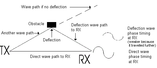
Here goes for a quick explanation of the problem (with suitable apologies for the superficiality). Direct radio waves will obviously travel in a straight line from the transmitter (TX) to the receiver (RX). But there are other waves inside the signal 'cone' (or circle if the antenna is a omni). If these other waves don't bump into anything (there are no obstacles) they will just travel off into the night until overcome with exhaustion. But if they bump into something (a deflection) they may end up at the RX antenna and if they are out of phase with the straight line signals they may have a phase cancelling effect - they will reduce the power of the arriving signal. The magnitude of the phase cancelling effect is a function of the signal strength (the longer the distance the waves have travelled the lower the signal strength) and how out of phase (always described in terms of an angle) is the deflected signal. See diagram 1 below.

Diagram 1 - Phase cancelling effects from deflections (bumps)
Phase Cancellation
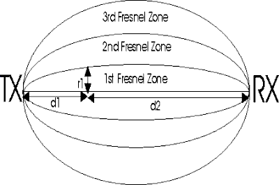
Fresnel provided a means to calculate how out of phase the bumps (deflections) between the transmission source (TX) and the receptor (RX) will be. Each Fresnel zone is an ellipsoidal shape ('sausage like' to the rest of us) as shown below. Deflections (bumps) from obstacles which occur anywhere in zone 1 will, if they arrive at the receptor (RX), create signals that will be 0 to 90o out of phase, in zone 2 they will be 90 to 270o out of phase, in zone 3 they will be 270 to 450o out of phase and so on. Even numbered zones are bad'ish (they have the maximum phase cancelling effect) and odd numbered zones are good'ish (they may actually add to the signal power). The signal strength (and hence the magnitude of the phase cancelling effect) is strongest in zone 1 and decreases in each successive zone simply because wave paths get longer (and signals get weaker) the further they are from the direct line from transmitter (TX) to receptor (RX). Because the Fresnel zone is ellipsoidal, at any arbitrary point which is d1 distance from the transmitter (TX) and d2 distance from the receptor (RX) each Fresnel zone has a unique radius value of r1. Fresnel's equation allow us to calculate this unique radius (r1) given the value of either d1 or d2. See diagram 2.

Diagram 2 - Fresnel zones
OK, so what's the big deal
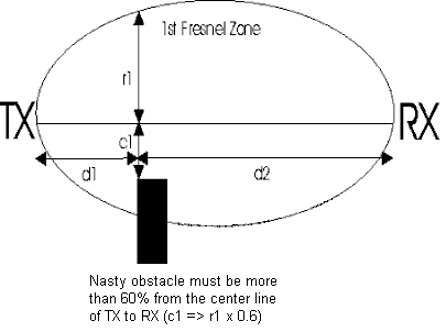
The big deal is this. To maximise RX strength you need to minimise the effect of the out of phase signals. To do that you must make sure the strongest signals don't bump into anything - they have the maximum chance of getting to the RX location. The strongest signals are the ones closest to the direct line between TX and RX and always lie in the 1st Fresnel Zone. The rule of thumb is that 60% of the 1st Fresnel zone must be clear of obstacles If you have a building, say, that is a distance d1 from the TX antenna and d2 from the RX antenna then it must not be closer than 60% of r1 measured from the centre line of sight (shown as c1 in diagram 3). You may need to juggle the antenna positioning to ensure this 60% zone is clear (you will also see this 60% figure written as 0.6 just to confuse). See diagram 3.

Diagram 3 - Fresnel zone clearance
The earth is in the way
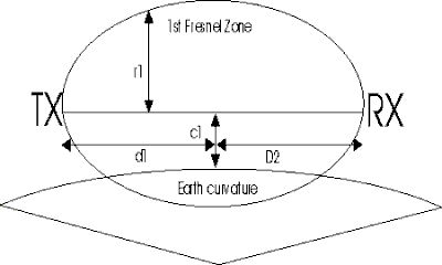
Finally on longer links especially (> 3Km or 2 miles) you will frequently see discussions about Fresnel zones and the curvature of the earth (though it can have an impact at very much closer distances). The reason: even if you are shooting a link across flat ground with no apparent obstacles, eventually the ground itself becomes the obstacle and can easily get inside the 60% clearance zone. Solution: lift the antenna higher to make sure the earth stays out of your way! In diagram 4 d1 and d2 are the same (the mid point) so the distance of the direct line of sight to the earth (c1) must be more than 60% of r1. Our Fresnel Calculator gives the earth's height (or bulge) at the mid point of the link.

Diagram 4 - Fresnel zone and earth curvature
Problems, comments, suggestions, corrections (including broken links) or something to add? Please take the time from a busy life to 'mail us' (at top of screen), the webmaster (below) or info-support at zytrax. You will have a warm inner glow for the rest of the day.


