[an error occurred while processing this directive]
Tech Stuff - LAN and Telephones
We get a lot of mail about carrying LAN and telephony on the same cables. This page is designed to give you some information to let YOU decide whether you want to do this or not. It is not easy and you should be very comfortable with all the information here before you set out to destroy your premises wiring!
This is not an activity to undertake between TV shows but may, depending on your current knowledge, require some serious effort and may (heaven forfend) REQUIRE YOU TO THINK. You have been warned.
Contents:
Before you Begin
If you mix LAN and Telephony on the same wiring it will be non-standard. Put simply this means that you may not be able to take advantage of certain new applications that use the currently unused pairs in 100base-TX. Increasingly we are seeing 'Power-over-Ethernet (PoE)' systems which can make use of both spare pairs in 1000base-TX wiring and will likely provide power for VoIP or other technologies. If you mix PoE systems with non-standard wiring you could destroy or damage equipment and have other unpleasant or harmful effects. 1000base-T (gigabit Ethernet) uses all 4 pairs (8 conductors) and cannot be used with mixed LAN and telephony wiring.
DISCLAIMER: THE INFORMATION PRESENTED HERE IS NOT WARRANTED IN ANY WAY. PROCEED AT YOUR OWN RISK. NON-STANDARD WIRING MAY HAVE UNINTENDED OR HARMFUL CONSEQUENCES BOTH NOW AND IN THE FUTURE.
Electricity and Telephone Wiring: When the telephone rings, and depending on how close you are to the central office, there may be a hazardous voltage (up to 150 volts) on the line. Take sensible precautions such as:
- Disconnect phone lines until the last possible moment.
- If you can stop incoming calls using a 'class' service or a 'do-not-disturb' feature use it while you are actively working on the wiring.
- Make sure your footwear has good insulation characteristics.
- Make sure all your tools have insulated handles
- Avoid touching bare wires
- NEVER work near water
- Never work on wiring during an electrical storm
- If you smell gas stop and have it investigated immediately by an expert

FEASIBILTY - and more CAUTION
Many newer home and office cable installations use category 5 or 5e wiring. In many cases this carries just telephony or LAN traffic. We are frequently asked whether it can carry both LAN and Telephony since pulling additional wires can be a difficult, messy, expensive or downright impossible.
Since 10base-T or 100base-TX wiring uses 2 pairs (4 wires) and each analog phone connection uses a single pair (2 wires) you can, subject to limitations, run 2 telephone connections and LAN traffic on category 5(e) wiring but IF AND ONLY IF YOU CAN ANSWER YES TO ALL THE ITEMS BELOW.
- The maximum speed of your LAN will be 100M bit/sec.
- ALL the wiring that is planned to carry LAN or LAN and Telephony is Category 5 or 5e standard.
- You have no equipment installed or planned to be installed that will use Power-over-Ethernet (802.3at) using Alternative B wiring (802.3at allows Alternative A wiring for PoE to use only the standard LAN signal pairs 1,2 and 3,6 so this is compatible with the mixed wiring here).
- You have standard one pair (2-wire) analog phones throughout the premises.
- Every access point that will carry LAN or LAN plus telephony traffic is wired as a Star or Home-run.
If you are NOT positive about the answers to the above STOP NOW and either find the definitive answers or take-up origami.
Note: If you are doing the wiring - pull two separate wires (one to carry telephony and one to carry LAN - both should be cat 5e or 6) to a single multi-use jack. This will save a lot of hassle. Only use these techniques if you have no other choice.
Another Note: If you ARE doing the wiring consider pulling a good quality video cable at the same time, for example, RG6 or similar even if you have no immediate plans for its use - or then again you may enjoy crawling around in your attic up to your nose in dust and want to do it again. The keystone wall plates described below typically have video outlet key inserts.
DO IT ONCE AND DO IT RIGHT
OK you are still hanging in there - or perhaps this is more interesting than Origami (just who is this Origami person?).
You want this stuff to last. Right? You never want to touch this stuff again. Right? You want to do other things with your life. Right? You never want to crawl around your attic and basement again. Right? DO IT ONCE AND DO IT RIGHT. EVEN IF YOU HAVE TO MISS TWO TV SHOWS INSTEAD OF THE ONE THAT YOU PLANNED.
The configuration
These notes assume that you want one or more LAN connections and that you want to carry both telephony and LAN on the same cables.
Planning - the Hard Work
If you thought this was going to be easy - forget it - go take-up floral arrangements, golf or watch paint dry.
Before you start you need to do three things
Invest in (or borrow) the right tools. You will need as a minimum:
A punch down tool (for the wall jacks and any cross-connects).
Labels for marking both ends of each connection/cable if this has not already been done.
If your cabling is not numbered (or otherwise clearly identified) or you are suspicious you may need cable detection equipment. This equipment normally has two parts. One part injects a tone onto a wire and the other end is like a wand and allows you to find the end that is carrying the tone. This type of equipment can vary enormously in price and quality ($100 to $500).
If you have to make up LAN or Telephone end cables then you will need a crimp tool suitable for RJ45 (8 wire - 4 pair) and RJ111/12 (6 wire) connectors. Get the best one you can afford. They typically come with a built-in cable-cutter and wire-stripper. Make a few practice cables and test them until you get it right - it's harder than it looks.
If you are pulling the cable - espcially in tight spots - get what is typically called a cable fisher. It's a roll of spring steel with a hook at the end for pushing and pulling wire. Indispensable.
Optional. LAN cable testers are available in a range of prices from $10s to $100s of dollars and if you are going to do a lot of wiring are well worth the investment since they let you check your work at each stage in the process.
Make a sketch plan of your current wiring and note the colours used at both ends of each connection and the equipment connected or to be connected. Now allocate, if it is has not already been done, a unique ID or number to each connection and then label both ends of the cable - preferably with the same number - as soon as you have found both ends of it! Remember you don't want to do this again.
Finding both ends of an installed cable run is no easy task and you may need to use cable detection equipment to do so (see above). MAKE NO ASSUMPTIONS. Someone else, far less skilled than you, may have already installed non-standard features.
Document your new design on a new sketch plan, because:
In three days time YOU will have forgotten what you did.
You may sell or move from your premises and it's pretty unfriendly, if not dangerous, to leave your non-standard wiring undocumented.
Your design should cover as a minimum the following elements:
YOUR COLOUR CODING STANDARD. Start with the LAN and select either 568A or 568B colour coding. This scheme defines the 2 pairs (4 wires) for the LAN. Select one spare pair to carry the first Telephony connection and the final pair to carry the second telephony connection. Stick to this standard everywhere EVEN IF IT MEANS RE-WIRING EXISTING CONNECTIONS. The alternate is that you will have non-non-standard wiring. Not even your mother will be able to help clean up that mess.
The following is an example of such an allocation (based on 568B color coding) but it is not the only one possible.
| Pin No. |
strand color |
Name |
| 1 |
white and orange |
LAN (TX_D1+) |
| 2 |
orange |
LAN (TX_D1-) |
| 3 |
white and green |
LAN (RX_D2+) |
| 4 |
blue |
Telephone 1 |
| 5 |
white and blue |
Telephone 1 |
| 6 |
green |
LAN (RX_D2-) |
| 7 |
white and brown |
Telephone 2 |
| 8 |
brown |
Telephone 2 |
All the access points/jacks, to include the new ones you are installing, the connections to be supported, for example, kitchen - 2 telephones, den - 2 telephones and LAN and so on.
Gazing at Stars and 'Home Runs'
It's important that you understand the concept of Star Wiring topology (sometimes called home-run wiring) before you start. All LAN wiring uses a star topology.
Star (or home-run) wiring means that each access point (wall-plate) is directly run back to a central or home location (normally in the basement or where the telephone service enters the premises) with no breaks. Many, if not most, older premises and even quite recent ones use multi-drop telephone wiring which allows multiple phone access points on a single cable run.
This is perfectly permissible for phone systems (typically up to 5 such drops can be used) but, MULTI-DROP WIRING CANNOT SUPPORT LAN TRAFFIC. You must have STAR WIRING to each access point that will carry LAN traffic. Diagram 1 illustrates the differences in wiring topologies.
Diagram 1 - Star vs Multi-drop wiring
Equipment - Cables and Connectors
This section provides some notes about what type of cables and connectors you can use.
Today (2006) you should be using Category 5e wiring which is typically competitively priced. You can however use category 5 for telephony and 100MB LANS but this may be flaky if you want to upgrade to GB LAN. If you want to invest for the future use Category 6 wiring.
Cables (5, 5e or 6) come in two forms. Stranded - each conductor is made up of multiple smaller wires and Solid - each conductor has a single wire. Stranded cable is typically more expensive than solid cable. In general, cables that are rarely moved, such as runs inside walls or backbone wiring, use solid cabling. The exception to this is where you need to bend round very tight corners (the bend radius is less than 6 inches or 15cm) in which case you should use stranded cable for this purpose. Any cable which is moved or unplugged frequently, such as PC to wall plate cables, should use stranded cable.
Stranded and solid cables MUST use the appropriate connectors. Do not be tempted to mix them. It is sometimes very difficult to tell from a connector description which is which. In general avoid these connectors because if the supplier does not know - what chance has the poor user. In general, connectors designed for wall plates assume solid cable.
Jacks, Access Points and Wall-plates
The next item on the agenda is getting the right connections at the room Access Point Wall-Plates (or Jacks - we're going to use the term Access Point from here on (AP for short)).
There is an enormous choice of Access Point wall-plates available today from reputable network suppliers with almost every combination of voice, data and video connections. The most flexible are called keystone wall-plates and provide blank plates with the right number of empty holes (available with typically 1, 2, 3, 4 and 6 holes). Recessed and surface mount options, as well as a whole range of colours, are typically available.
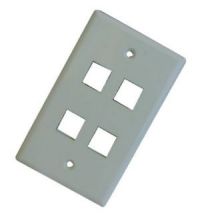
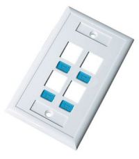
Keystone wall plate examples
Into these 'keystone' holes you plug the keystone jacks of the type that you need e.g. 1 RJ45 (for LAN) and 1 or 2 RJ11/12 (for Telephony), video etc. A wide range of colors is usually available. Both punch-down and 'tool-less' versions are now available.
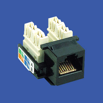
Keystone jack example - punch-down
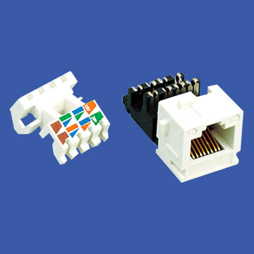
Keystone jack example - tool-less
End connections are critical and if poorly done can be a huge source of loss and poor performance. Use high quality and correctly rated connectors. DO NOT BE TEMPTED TO SKIMP COST AND USE EXISTING WALL-PLATES IF THEY ARE NOT SUITABLE JUST BECAUSE THEY ARE THERE. YOU WILL REGRET THIS WITHIN MINUTES. DO IT ONCE AND DO IT RIGHT.
Command Central
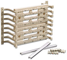
In a Star Network eveything interesting happens at our central or home location which is typically situated where the telephone wiring enters the home or premises. Here we will install our Hub/Switch and carry out all our cross connections using a Wiring or Punch-down block such as 110 type, BIX or Krone. We show a common 110 type below. They come in all sizes but each 'bar' typically has 25 punch-down slots - each 'bar' will take 3 incoming cables.
Hub vs Switch
The price difference between a Switch and a Hub is almost vanishly small these days. Unless budget really is a key issue we would suggest a Switch. They come in all kinds of sizes 4, 5, 8, 16 and 24 ports. Some have the ports at the back and leds at the front, others put both at the front (we illustrate both types below) Note: We show particular vendor products for illustration only. Any suitable Switch or Hub will do the job we do not endorse or recommend any particular vendor product.
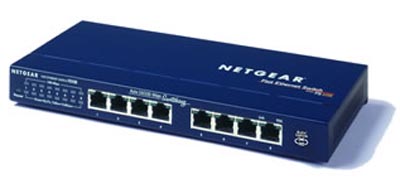
RJ45 and LEDS at front
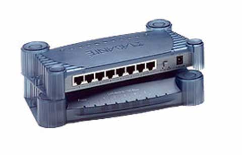
RJ45 at Rear LEDS at front
The general specification - irrespective of whether it's a switch or hub - is:
- Minimum number of ports equal to the most systems you can think of connecting plus some (say 2) ('cos you are going to change your mind!)
- 10/100 Mbit/s auto sensing
- LINK LED for each port
- 10/100 LED for each port
They typically come with lots of other features e.g. Full/Half Duplex, managed or unmanaged - your budget will figure out what else you want or can afford.
So let's Boogie
We are going to:
- Run a cable from each room where we want to install multiple connections to our central location (typically where the telephones enter the house)
- Add and wire the Access Point wall-plates in each required room
- Install the Hub or Switch at the central location
- Punch-down our incoming (from room) cables onto the puch-block
- Cross-connect from the punch-block to the LAN and Telephone connections
Hang on a minute
This is a big job so spend a couple of minutes reading these notes:
- If you get this wrong your telephone system may not work - is this acceptable?
- It will probably take longer that you think - do you have the time?
- Take one step at a time - test as much as you can when the step is complete.
- If you need your phone system during the week - start on Friday evening - gives you Saturday to run round the stores to get everything you forgot!
- Do all the LAN cross-connections before you touch your telephone system.
- Do a single - least important - room first. Figure the time to finish the whole job and plan on that basis.
- Read the troubleshooting hints before you start - you will probably need them at some point!
It's all Twisted
Making good end connections is both the key to success and tougher than it looks. The following notes may help:
Wall Plate connections
- Practice making connections until you get it right every time - especially before you destroy cables you just spend 2 hours fitting.
- Make sure you have 6 - 8 inches of slack cable in case you make one or more mistakes.
- If you make a mistake throw away the connector. Never be tempted to re-use connectors. They may work but one day they may stop and you will spend hours trying to find the problem.
- When cutting the exterior cover of the cable be very careful not to cut the insulation cover of the conductors since this can cause shorts. Shorts are not good.
- When making multiple connections in a keystone wall plate expose the MINIMUM amount of conductor necessary to complete the job.
- Line up all the conductors according to the wiring standard you are using.
- Punch-down or connect all the wires.
- Carefully trim any excess conductors.
- Test the connections before fitting the wall plate.
RJ45 End Connectors
- Make and test practice cables until you get it right every time - especially before you destroy cables you just spend 2 hours fitting.
- When cutting the exterior cover of the cable be very careful not to cut the insulation cover of the conductors since this can cause shorts.
- Expose a maximum of 1 inch of individual conductors when preparing the cable for connection.
- Line up all the conductors according to the wiring standard you are using.
- Measure the cable and trim the conductor ends so they are are all the same length and no individual conductor wire is visible outside the plastic cover of the RJ45 connector.
- Carefully slide the prepared cable into the RJ45 connector making sure the end of the conductors reaches the end of the RJ45 connector.
- Using the crimp tool make the connection using one firm squeeze operation.
- Test the cable before fitting if possible.
- The RJ45 connector is the critical connection always use the highest quality connectors you can afford. The most common cause of connection faults is bad connectors.
Safety Information
Electricity and Telephone Wiring: When the telephone rings, and depending on how close you are to the central office, there may be a hazardous voltage (up to 150 volts) on the line. Take sensible precautions such as:
- Disconnect phone lines until the last possible moment.
- If you can stop incoming calls using a 'class' service or a 'do-not-disturb' feature use it while you are actively working on the wiring.
- Make sure your footwear has good insulation characteristics.
- Make sure all your tools have insulated handles
- Avoid touching bare wires
- NEVER work near water
- Never work on wiring during an electrical storm
- If you smell gas stop and have it investigated immediately by an expert
Now where did I put the telephone...
When you are wiring each access point be consistent and methodical. Either label each access point on the front cover (LAN, Telephone 1 etc) or use the same convention everywhere. Diagram 2 show one possible wall jack configuration.
Diagram 2 - Possible wall plate configuration
If you don't use a connection in a particular room - use a blank insert in its place don't change its position, for example, in EVERY room the second line is the bottom right position or whatever your stanard is.
We're starting to get a little Punchy
We are going terminate our 8 wire (4 pair) cat 5, 5e or 6 wires to the wiring block and then cross connect them to their destinations. Each LAN connection will go to a separate port on a HUB or Switch and the telephone pairs will go to our common telephone line(s). Diagram 3 shows this conceptually. Each pair is shown as single colored line to try and keep the level of detail as low as possible to give on overview of what we are trying to achieve. The REDs lines will connect from pairs 1,2 and 3,6 (using our suggested wiring scheme), the BLUE line represents Telephone Line 1 (pair 4,5) and the GREEN line represents Telephone Line 2 (pairs 7,8). Note: The color of the lines in diagram 3 should not be confused with the wire colors as shown in diagram 4. The colors were selected simply beause they provide the highest contrast on a white background and for no other reason. Diagram 4 shows the real wiring color as it appears on cat 5, cat 5e and 6 cables.
Diagram 3 - Cross Connect Overview
We have Lift-Off Houston
The following notes and diagrams assume that you are using the proposed color coding scheme. See diagram 4 below showing cat 5, 5e and 6 wiring colors.
Notes:
Punch all 8 conductors on each incoming (from rooms) wire onto the punch-block - use the same color sequence for every wire - most sensibly use the pin number sequence.
Keep the exposed conductor length as short as possible (max. 1", 2.5cm).
Make up the LAN-HUB/Switch 'pigtail' cables (straight) with an RJ45 connector on one end and separate exposed connectors on the other end. These cables should be long enough to go from the punch-down block to your HUB/Switch.
Trim the 4 unused conductors from this cable (blue, blue/white, brown, brown/white).
Punch each conductor of this cable onto the same colored conductor on the selected incoming cable - keep the exposed conductor length as short as possible (max. 1", 2.5cm).
Connect a PC into the LAN connection in the room from which the cable comes (you did remember to keep that diagram and you did label the cable ends didn't you?) and confirm you have a LINK on the Hub/Switch. If not stop and fix the problem before doing anything else.
Terminate each of the incoming telephone line wires on a SCREW terminal.
Punch one end of a JUMPER wire onto the relevant conductor of the incoming (from room) cable. Expose the metal of the conductor on the other end and connect it to the appropriate screw terminal of the telephone line. Note: In the diagram below the 'jumper wire' is shown as the same color as the conductor it is connected to, while this may be useful, it is not essential. Any wire color may be used.
Repeat the process above for each incoming (from room) cable.
Never try and punch more than two conductors into a single slot on the punch down block.
Diagram 4 - Detailed Color-Coded Wiring Diagram
We have (hopefully) Lift-off
Run around the house checking that everything works, rejoice and finish off watching that second TV program you almost missed. Phew!
And if it all goes Pear-shaped
Pear-shaped is a quaint British expression meaning ... well.. things are not so good.
Trouble Shooting Hints
Regretably there a lot of things that can go wrong - the following notes may help you:
Don't Panic - you can always make all your phone calls from the basement! Seriously: panic is not a very useful emotion - though perfectly natural. If you feel either panicky or tired: STOP. Go get some sleep or have a rest and something to eat - it really will be better when you start again.
Create and keep a 'gold standard', that is, use a single PC/laptop connect it directly to the hub via a cable that is long enough to strech from every room in the house to the hub - confirm that the Hub/Switch LINK led works every time and preferably use a PC that has a LINK led on its LAN card. Keep this configuration and move it to every room when you test the connection. At least you know something works. Plug this configuration into the wall connector under test and if you don't get LINK - it's your wall cable/punch-down cross-connect.
The long cable and gold standard PC rig is designed to help isolate problems. An alternative strategy is to take the PC and its cable from the room in which it will be installed to the switch and confirm it works there. Depends on your own circumstances which stategy is more convenient or less exhausting. Of course before you do start dragging cables or lugging PCs around try the connection first. It may work first time. Then again it may not......
LAN cable testers are available in a range of prices from $10s to $100s of dollars and if you are going to do a lot of wiring are well worth the investment.
Test every PC to wall LAN cable before you start by using them to connect to the Hub/Switch locally - you don't want to rip-up your installed cable until you are sure it's at fault.
Make no assumptions - test or check everything.
Buy a cheap magnifying glass - its almost impossible to do a visual check of punch-down connections (or any other for that matter) without one.
Use a 'continuity tester' or a volt-meter to check individual conductors in cables.
Problems, comments, suggestions, corrections (including broken links) or something to add? Please take the time from a busy life to 'mail us' (at top of screen), the webmaster (below) or info-support at zytrax. You will have a warm inner glow for the rest of the day.


